The Basics of Coil Winding
Comments Off on The Basics of Coil WindingCoil winding involves wrapping a wire around a cylindrical object in a spiral-like shape to produce a standalone coil or a coil on a toroid, bobbin, or other type of center support. The coil may be made of one or more layers of wires depending on its intended application.
The following factors influence the type of coil winding used in an application:
- Dimensions, shape, and geometry of the coil design
- Inductance properties
- Insulation strength
- Magnetic field requirements
- Available space
- Specific location of the coil in the device or system
Due to these factors, coil winding is a complex art and science. Learn more about the basics of coil winding and the different types of coil winding techniques.
Coil Winding: Basics and Machinery
An electric coil is an electrical conductor with a series of conductive wires wrapped around a core. Found in electric generators, motors, electromagnets, and inductors, electric coils provide a reliable, consistent method of inductance, effectively opposing a current’s flow.
Utilizing different types of coil winding techniques allows engineers to create single or multiple-layer coils for electronic components that meet voltage, electrical current, and heat insulation requirements.
Manual and automated winding systems are commonly used in the production of coils. The factors which influence which option is utilized includes specific design parameters and volume requirements.
As manual methods have evolved into automated processes, coil winding machinery offers enhanced precision, efficiency, and quality, benefiting most applications and industries.
Diverse Coil Winding Techniques
Engineers select the appropriate method of coil winding based on space availability, coil location, and other design specifications. Each technique offers a unique set of features and characteristics.
Wild Coil Winding

Wild coil winding is a quick and easy method that wraps the wire unevenly in a cross-winding pattern. The random wire placement results in a wider range of electric coil resistances and a wider distribution of wire lengths on the coil’s body. This type of coil winding is commonly used in high-volume mass production and is best suited for the following applications:
- Devices with small wire gauges
- Ignition coils
- Relay coils
- Small electric motors
- Small transformers
Helical Coil Winding

In helical coil winding, the wire is uniformly wound in layers around a cone or cylinder to create a three-dimensional spiral shape. Each layer contains wires wound in the direction of movement, alternating between right-hand and left-hand, with each layer of wire resting in the gaps of the underlying layer. Helical coil winding is used in low-voltage windings and can include several strands or up to a hundred continuously parallel wires.
Orthocyclical Coil Winding

Orthocyclic winding is an efficient method that allows each layer of wire to fit into the grooves of the layer beneath it. Its high fill factor of 90% creates a strong magnetic field. This winding pattern allows for maximum usage of space and continues over each layer. Every turn occurs parallel to the next, with only a fractional shift between each layer.
Sandwich Coil Winding
Sandwich coil winding is a unique layered design where high-voltage windings are sandwiched between two low-voltage layers to reduce leakage flux. This type of coil winding is primarily used in transformer production and looks like a series of discs.
Bobbin Coil Winding

A bobbin coil consists of wire wrapped around a bobbin, which will vary based on current and voltage levels, operating frequency, and rating. Bobbin coils are often used in power conversion units and switch-mode power supplies, as well as many other applications.
Contact Custom Coils, Inc. for All Your Coil Winding Needs
Automated and manual winding machinery and various types of coil-winding techniques play a critical role in the performance of the intended electrical device. At Custom Coils, Inc., we have the knowledge and expertise to perform the method that best suits the demands of your specific application.
Contact us or request a quote to learn more about coil winding and how Custom Coils can serve your needs.
Solenoids: Working Principle,
Types & Applications
Comments Off on Solenoids: Working Principle,Types & Applications
A solenoid is a variety of electromagnet consisting of a copper wire coil wound tightly into a helix, an iron or steel housing, and a mobile plunger made of magnetic material. When an electric current passes through the coil, the solenoid produces a magnetic field and converts that magnetic energy into mechanical motion. Essentially, a solenoid converts electrical energy into mechanical work through electromagnetic forces. For example, solenoids are often used as a valve to actuate a push or pull force on a magnetic component in a device. Solenoids can also act as a switch in electromechanical devices. These electromagnetic devices are used in hundreds of everyday applications from doorbells to car ignition systems.
Custom Coils designs and develops quality solenoids to meet the needs of your application. We work efficiently and expertly to create specialty coils for our valued customers.
How Does a Solenoid Work?
When an electric current is applied to a solenoid, it creates a powerful magnetic field that attracts or repels a magnetic material, ie magnetic plunger, to move inside of its housing. As the plunger moves back and forth, it creates the mechanical motion that powers the intended component.
Solenoid magnets have an advantage over conventional permanent magnets because their magnetism can be switched on or off as needed by removing or applying the electrical current. You can adjust the strength of the magnetic pull by increasing or decreasing the electrical current. Additionally, the direction of motion can be reversed based on the direction of current flow through the solenoid.
There are two basic types of solenoids: valve and electric. In valve solenoids, a constant electric current is applied to the solenoid. Once activated, the piston or plunger retracts to open the valve that would otherwise block the flow of material. Once the electromagnetic field is broken, the solenoid is deactivated and the valve will close.
Electric solenoids are used to close circuits to allow engines to run. When the solenoid receives the electric current it pulls nearby metal components in place to create a closed circuit. Constant electric current is required to keep the circuit closed and the engine running.

Types of Solenoids
- AC-Laminated Solenoid: These solenoids comprise a wire coil and a metal core made with laminated metal, which helps reduce stray currents and optimizes the solenoid’s performance. AC-laminated solenoids have an inrush current, which delivers a greater amount of force in the initial stroke. This also means they can deliver more strokes than DC-laminated solenoids. Common applications of AC-laminated solenoids include locks, medical devices, industrial equipment, vehicles, and other equipment that need immediate operation.
- DC C-Frame Solenoid: Some applications may also use a DC C-frame solenoid, which features a C-shaped frame that wraps around the wire coil. This solenoid uses a stroke operation with more control, making it suitable for many everyday applications, like circuit breakers, camera shutters, scanners, coin counters, and gaming machines. Though it utilizes DC configuration, DC C-frame solenoids are compatible with AC power equipment.
- DC D-Frame Solenoid: Like C-frame solenoids, DC D-frame solenoids operate with more controlled strokes and are compatible with AC power applications. The main difference is that the D-shaped frame is made with two joined pieces that shield the coil. ATM machines, gaming machines, and gas- and blood-analyzing equipment often use these solenoids.
- Linear Solenoid: This is one of the most widely recognized solenoids. Linear solenoids feature a coil-wrapped metal core, delivering pushing or pulling force to operate a piece of equipment. This operation makes it popular for use in many starting devices, such as vehicle ignition systems. Linear solenoids are also ideal for use in electric locks to enable the door to withstand significant forces when locked.
- Rotary Solenoid: If an application needs a simple automatic control process, it may use a rotary solenoid, which has the same essential components as other solenoids but with a unique mode of operation. Rotary solenoids function using a metal core situated on a grooved disc. The grooves are sized according to the slots on the solenoid’s body, and ball bearings allow for improved ease of motion. When it’s powered on, the core withdraws into the solenoid’s body and the disc core rotates. When it’s powered off, a spring pushes the disc core back to its starting position. Because they are more robust than other types of solenoids, rotary solenoids are often used in industrial applications like automated shutters and lasers.
Applications for Solenoids
Without realizing it, you use solenoids every day. Solenoids vary in size and power, making them suitable for countless applications. Powerful solenoids consist of many coils, create strong magnetic fields, and can be used to power large machinery. A smaller, less powerful solenoid can be used for smaller functions like ringing a doorbell. Some of the more common applications for solenoids include:
- Mechanical or fluid control valves
- Starting a car
- Ringing a doorbell
- Door locking mechanisms
- Nail guns
- Air conditioning controls inside vehicles
- Powering signal systems in the railroad industry
While these simple but effective devices are used to actuate many common devices, they have become highly utilized in nontraditional physical motion applications, such Ion Beam Accelerator systems.
There are innumerable applications for solenoids, as any device that requires force to create mechanical movement can benefit from their functionality.
Custom Coils is Your Expert on Solenoid Design and Manufacturing
Solenoids are important devices in much of the technology we use daily. These devices are effective, versatile, and easy to implement in your systems. From conception to production, the experts at Custom Coils will partner with you to determine your specific needs and customize the right solenoid device for your application. Contact us to learn more about our services or request a quote today.
A Guide to Magnetic Particle Imaging (MPI)
Comments Off on A Guide to Magnetic Particle Imaging (MPI)")
Medical professionals rely on access to high-quality preclinical imaging tools to monitor healthy and diseased tissue, make diagnoses, and develop treatment plans. Three tomographic preclinical imaging options have been available over the last few decades: positron-emission tomography (PET), computed tomography (CT), and magnetic resonance imaging (MRI).
Each has its own drawbacks, from using ionizing radiation to achieve images or lacking the capability for real-time 3D volume imaging. However, magnetic particle imaging (MPI), a new, cutting-edge preclinical imaging technology, promises to provide superior insight into our biology and diseases’ effects on it down to the molecular level.
What Is Magnetic Particle Imaging (MPI)?
MPI creates three-dimensional, finely detailed images of organs, tissues, cells, and molecular-level specimens. It utilizes specialized imaging hardware coupled with tracers of specific metal particles called super-paramagnetic iron oxides (SPIOs). Once a medical professional has introduced the tracers into the patient’s targeted systems, the patient moves to the MPI scanner’s imaging region, where they’re exposed to a magnetic field. The SPIOs interact with the equipment’s field gradient, creating detailed particle images of the examined tissue, system, or region with optimal resolution and contrast.
The Problems MPI Solves
MPI systems address two critical issues that other modern-day scanning options struggle with:
- Profusion imaging. Medical professionals run billions of dollars worth of profusion scans each year to track the flow of blood through tissue or an organ like the heart or brain. However, the images often lack the detail or resolution that would allow for early medical detection and intervention.
- Radiation and contrast agents. Scanning technology often requires the use of radioactive tracing elements and contrast agents. Patients cannot regularly be exposed to these volatile substances, so medical professionals can only take a limited number of scans, further exacerbating the risk of missed disease indicators.
Alternatively, MPI can pick up on small abnormalities, so it assists with diagnosing diseases sooner because of the superior sensitivity of the technology. Medical professionals won’t need a high volume of SPIO tracers to produce an image, and SPIOs are also safer for patients.
How MPI Works
Rather than detecting tissue itself, MPI works by tracking the movement of SPIO particles in specific tissues, organs, or areas of the body. Medical professionals can even target the application of tracers to focus on a single factor, like CAR T-cells.
These systems have two permanent, sizable MPI magnets directed at each other, generating a strong magnetic field. However, in the middle of the MPI magnetic field, there is a field-free, or fueled-free, region (FFR) that generates little magnetic force in a known location. This field-free region will interact with any SPIO nanoparticles with which it crosses paths, making these particles flip, which the MPI receiver coil then interprets as a signal.
The MPI moves the magnetic field very quickly over the patient in the equipment’s imaging region, causing all of the SPIO particles to flip. These signals, as the technology understands them, pinpoint a specific location and MPI translates them into a quantitative, finely detailed 3D image through tracer distribution.
How MPI Differs From Other Imaging Techniques
MPI operates very differently from other imaging methods, providing a higher degree of image quality. Though they have different magnet architectures, MPI is often compared to MRI, which uses magnets to identify resonance from the H nucleus and other nuclear spins. MRI technology has common applications in anatomical imaging but doesn’t provide the same fine-tuned imaging on a small scale that MPI can.
Rather than picking up on nuclear signals, MPI detects nanoparticles’ magnetization, allowing for a much greater degree of sensitivity and better success in cellular imaging tasks. Compared to PET imaging and MRIs, MPI is also a faster imaging option.
Applications of MPI
With various uses in the medical sector, key MPI applications include:
- Early cancer, cerebrovascular, and cardiovascular disease detection. With sub-micromolar sensitivity, MPI doesn’t have to use radiation but can still achieve reliable screening results for earlier, better illness detection.
- Perfusion imaging of the heart. Similarly, its sensitivity allows healthcare professionals to receive enhanced heart images for better evaluation.
- Monitoring treatment progress. Given its spatial and temporal resolution capabilities with a zero background signal for endogenous tissue, use of long circulation half-life particulate, and speedy access, MPI is adept at monitoring ongoing treatments.
Benefits of MPI
MPI is particularly advantageous because of its superior sensitivity, speed, and safety compared to other imaging options. It doesn’t rely on radiation like PET or x-rays like CT, so it makes more frequent screenings possible. Also, the system is easy to operate, even without dedicated personnel, so medical researchers can gather data on their own.
Most importantly, MPI produces industry-best, high-resolution images that can dramatically improve early detection, diagnosis, and treatment development. It has the potential to one day scale from preclinical to clinical applications as an alternative to radiation-using PET and SPECT scans.
Custom Coils Provides Magnetic Coils for the Medical Industry
Coils and electromagnetic assemblies are critical to the efficiency and dependability of advanced imaging and scanning technologies. Our expert team works with companies in the demanding medical and research areas of this sector to create high-quality, industry-compliant coils, inductors, and electromagnets. We understand that, particularly in critical industries, there is no one-size-fits-all solution, and so we draw on decades of experience to collaborate with you and find the material and design that will ensure accuracy and longevity in your product. Contact us to learn more about our capabilities for your components’ full development cycle, or request a quote today for pricing details.
Electromagnets in the Aerospace Industry: Thrusters
Comments Off on Electromagnets in the Aerospace Industry: Thrusters
Electromagnetic propulsion (EMP) requires two primary components: an electromagnet to generate the magnetic field and a propulsion component. EMP uses a current from the magnetic field to accelerate the object. Through Lorenz Force, the electrified conductor encounters a force in a perpendicular direction to the magnetic field and the current. If a liquid or gas is used for propulsion instead of a conductor, this force is called Magneto Hydro Dynamic drive.
The concept of electric propulsion is gaining popularity in the aerospace industry for use as a spacecraft thruster. For decades, the aerospace industry has led research into electric propulsion, focusing on electric propulsion diagnostics. The aerospace industry has long applied advanced diagnostics to thruster characterization, and now it is using various plasma probes to analyze the electric potential, density, and electron temperature of plasma. Aerospace researchers were the first to characterize electric propulsion thrusters using various diagnostic tools, including electromagnetic radiation measurement.
How Electromagnetic Propulsion Will Work
While space travel has thus far been limited to chemically-propelled rocket engines, in the early 21st century, antimatter, nuclear fusion, and light propulsion techniques are becoming promising means for space travel. New spacecraft without a means of propellant are also being introduced. These spacecraft would be moved through space using electromagnets.
At very low temperatures, electromagnets exhibit unique behavior—once electricity is applied, they vibrate for a few nanoseconds. Researchers hypothesize that if the vibrations are contained in a single direction, the jolt could propel the spacecraft further and faster than any other propulsion method can.
Types of Thrusters Used in Space Applications
Space applications rely on the following types of thrusters:
- Field Emission Electric Propulsion: This type of propulsion relies on indium, cesium, or another metal ion. It applies a potential difference of several kilovolts between accelerator electrodes and an emitter, accelerating the ions at high speeds. Satellites use field emission electric propulsion for precision direction and altitude control.
- Gridded Ion Thruster: This is a thrust system that uses electrostatic forces to accelerate ions. Negatively charged electrodes on the thruster’s downstream end create the electric field to facilitate acceleration. Coaxial apertures on the electrode function as lenses by focusing the ions. Positively charged upstream electrodes act as an accelerator grid, which attracts the ions and creates numerous ion jets. The amount of voltage applied affects the ions’ exhaust velocity in the beam.
- High-Efficiency Multistage Plasma Thruster: THALES Electron Devices in Germany developed this thruster, based on the ion thruster principle. It consumes propellant at a rate below 20% of the chemical system. The magnetic exit cusp confines low-energy neutralizer electrons to maintain a reduced plasma potential toward the thruster end, resulting in only a few electrons reaching the discharge channel’s exit cusp. The electrons that escape get trapped along the bent magnetic flux lines in spirals. The strong magnetic field gradient acts like a mirror, reflecting electrons in a radial direction.
- Hall Effect Thruster: This thrust system depends on electrostatic potential to accelerate ions. At the thruster’s open end, plasma creates a negative charge. A radial magnetic field equal to approximately 0.03 Tesla confines the electrons, while xenon gas or other propellant is fed through an anode and diffuses into the thruster’s channel, where the electrons ionize it. The propellant ions are accelerated between the cathode and anode.
- Magneto Plasma Dynamic Thruster: Based on the principle of Lorenz Force, Magneto Plasma Dynamic Thrusters eliminate the need for fuel combustion. Xenon, argon, neon, or another gas is ionized as it is fed into the accelerator chamber. The power source creates an electric and magnetic field, and the ionized gases are propelled out of the exhaust chamber, generating thrust.
- Pulse Plasma Thruster: As the most simple electric propulsion system, the pulse plasma thruster was used in 1960s Soviet-era spacecraft. An arc sent through fuel turns into plasma, which then travels between two capacitor-charged plates, charging the plasma and creating an electron flow. A strong electromagnetic field is created, exerting Lorenz Force and exhausting the accelerated plasma at high velocities. It functions on similar principles to a railgun.
- Quad Confinement Thruster: Using eight electromagnets, quad confinement thrusters generate a convex magnetic field with a central cusp and four outer cusps on the periphery. Accelerated ions pass through a Hall Effect static field to create thrust.
Contact Custom Coils for Your Electromagnet Needs!
Many applications depend on electromagnetic propulsion, including spacecraft and military aircraft. Electromagnetic propulsion is being researched for missile launches, long-range artillery, and direct-fire tank guns. It is also an essential technology in enabling all-electric submarines and naval ships in the future.
Custom Coils has been developing, testing, and manufacturing specialty coils since 1978. We specialize in creating custom coils for challenging applications, such as vacuum, zero gravity, and extreme temperature conditions typical to the aerospace industry. Contact us or request a quote to learn more about our capabilities.
Vacuum Casting
Comments Off on Vacuum Casting
Vacuum casting of wire coils removes air from the material surrounding the windings, which results in better thermal control of the component. This process also creates specific physical geometries that enhance the structural integrity of coils and allow for better compliance with space requirements. Vacuum casting is an effective process to protect coils from humidity and contaminants and is helpful in the reduction of winding noises.
Learn more about vacuum casting, how it works, and the benefits and applications of this process.
What Is Vacuum Casting?
Also known as vacuum impregnation, vacuum casting of wire coils involves the elimination of as much air from a structure as possible while replacing it with epoxy that has higher dielectric strength. Epoxies are special adhesives that will bond the wires and other components of the construction to create a more durable assembly.
How Does Vacuum Casting Work?
The vacuum casting process utilizes a chamber capable of handling temperature, vacuum, and pressure. This manufacturing process eliminates the voids or cracks in insulation that will eventually lead to the failure of a part. In coil manufacturing, vacuum casting and impregnation play a key role in protecting coils from corrosion and enhancing their mechanical and electrical characteristics.
The vacuum casting process requires a heated chamber and involves the following steps:
- The coil is placed in a mold within the chamber and heated to remove moisture.
- Air is removed from the chamber through a vacuum process.
- Epoxy/resin is separately degassed.
- Resin is injected into the chamber, filling the mold and fully covering the windings.
- Vacuum is slowly released and the component undergoes a curing process before it is removed from the mold.
Both traditional injection molding and vacuum casting require a mold tool that contains a cavity in the shape of the desired part.
Benefits of Vacuum Casting
A single master pattern can produce many copies of a component, reducing the money and time spent on the prototyping and product design stage. Some principal benefits of vacuum casting include:
- Thermal Properties: This process improves heat dissipation and is ideal for components subject to high temperatures.
- Physical Geometries: Vacuum casting allows for greater flexibility in terms of features and shapes as well as adhering to specific space constraints.
- Improved Coil Impregnation: Compared to other methods that can contain cracks or air pockets, vacuum casting is a more precise method of creating void-free insulation.
- Improved Electrical Performance and Durability: Eliminates partial discharge and reduces winding noises.
- Suitable for Various Applications: Vacuum casting allows manufacturers to customize parts for a wide range of properties and features designed into the mold that shapes the assembly.
Applications of Vacuum Casting
Typical uses of vacuum cast coils can include but are not limited to the following applications:
- Magnetic Resonance Imaging (MRI) Coils
- Current Transformers
- High-Voltage Ignition Coils
- Voltage Transformers
Vacuum Cast Components from Custom Coils
Since 1978, Custom Coils, Inc. has provided our valued customers with design-specific, high-quality manufactured coils, electromagnets, coil assemblies, inductors, solenoids, and more.
From our 23,000-square-foot facility in Benicia, California, we fulfill our customers’ manufacturing requirements, from small or single prototype coils to large-volume coil assemblies. Everything we manufacture is designed to match our customers’ specifications, and we integrate those requirements into a unique manufacturing solution to minimize cost while maximizing quality.
Contact us for more information on our vacuum casting and other custom coil manufacturing capabilities. You can also request a quote, providing us with specific details about your project.
Multi-coil Configurations and Their Effects
Comments Off on Multi-coil Configurations and Their Effects
With almost unlimited possible multi-coil configurations, it’s important to understand how standard multi-coil configurations interact when selecting custom coil components. While the electromagnetic properties of simpler multi-coil devices are easy to predict and control, managing more complex configurations requires a thorough understanding of how fields of basic multi-coil configurations interact.
Types of Multi-coil Configurations
Electrical engineers use various multi-coil designs to model the electromagnetic field of each configuration and determine its properties. These considerations are useful to achieve specific electromagnetic effects in various devices, and the qualities of any given multi-coil greatly affect its potential applications. The following are the most common standard multi-coil configurations, along with their associated electromagnetic properties and general applications.
- Dipole Magnet: Dipole magnets are capable of producing homogeneous magnetic fields across large distances. They stimulate particle motion in a circular plane perpendicular to the electromagnetic field, which is ideal for particle accelerators. By applying multiple dipoles along the same plane (collinear to the particle trajectory), it’s possible to increasingly bend the beam’s helical direction radially.
- Helmholtz Coil Configuration: A Helmholtz coil configuration is an almost completely uniform type of dipole magnet, consisting of two coils generating equal currents along the same axis. Because they have minimal variability, Helmholtz coils are useful for applications such as calibrating scientific instruments and canceling out the Earth’s magnetic field.
- Quadrupole Magnet: Because individual quadrupoles cannot focus along both vertical and horizontal axes at the same time, each quadrupole focuses along one plane, and defocuses along a plane perpendicular to it. There are actually two types of quadrupoles:
1. F quadrupoles, which focus horizontally
2. D quadrupoles, which focus verticallyPlacing both types of quadrupoles together directly cancels out their electromagnetic fields; however, placing them at a distance leaves certain portions of each quadrupole’s field intact, resulting in unique interference patterns. It’s then possible to control both the vertical and horizontal axes within an electromagnetic lattice produced by a quadrupole pair. By carefully spacing F and D quadrupoles, the direction and range of the magnetic beam’s focus is subject to control.
These properties make a carefully configured quadrupole pair ideal for controlling beam focus and particle generation. Depending on the type of lattice built by the interference pattern, it’s possible to send particle beams across large distances, form a complete ring, and achieve other specific effects.
Applications of Multi-coil Configurations
Electromagnetic devices often require an array of multi-coil configurations to achieve the desired effect. By combining different coils, it’s possible to control an electromagnetic field with precision control. The complexities of multi-coil systems rise with the use of less standard multi-coil configurations.
For custom, specialty coil designs, it’s critical to perform comprehensive modeling of any multi-coil configuration’s electromagnetic properties. Doing so makes numerous applications possible in the safest and most effective way while reducing unwanted electromagnetic interference.
Electromagnetic Field Effects
By altering the size, power, orientation, and placement of coils in relation to each other, basic coil configurations give way to more complex electromagnetic fields. Using different multi-coil configurations is fundamental to custom coil design, electronics manufacturing, and any application where electromagnetic residue might be problematic (such as motor shafts).
To control electromagnetic fields, it’s common to begin by designing and modifying more basic multi-coil configurations and determining their effect on the resulting electromagnetic lattice, beam direction(s), and other properties. In this way, technicians can design electromagnet coil products according to the specific needs of electronics manufacturers in numerous industries.
Contact Custom Coils for your Multi-coil Configuration Needs!
While potentially very complex, the foundations of multi-coil device configurations are relatively simple. By studying the effect of each coil on the electromagnetic field, Custom Coils’ experienced engineers achieve maximum control of these properties in our custom multi-coil devices.
If you have any need for specialty multi-coil products, request a quote from our highly knowledgeable project engineers. We can help you determine which multi-coil configuration is right for your design, including fully custom solutions.
How Do Electromagnetic Coils Work?
Comments Off on How Do Electromagnetic Coils Work?What are Electromagnetic Coils?
Comments Off on What are Electromagnetic Coils?
Coils are helically wound electrical wires that generate electromagnetic fields when exposed to an electrical current. They are vital parts of various devices, including electromagnets, solenoids, and inductors. A range of applications, from antennas to electric motors, rely on electromagnetic field generation from coils. Coils deliver many benefits and can be made from a diverse range of materials.
At Custom Coils, we are committed to producing high-quality, custom coils for our customers across industries. Our coil manufacturing expertise gives us the capabilities to meet your production requirements no matter the size. From design to production, we partner with you every step of the way.
What Are Coils?

A coil consists of a length of electrical wire with one or several helical turns to form a cylindrical shape. The coil wire carries an electrical current that allows the coil to function in several ways. A coil is suitable for use as a choke to provide inductance to create an electromotive force. When a core of soft iron is placed inside, coils gain electromagnetic capabilities. Solenoids are another type of coil that responds to variations in electrical currents to operate an attached plunger.
The following are applications that frequently rely on coils:
- Electromagnetic Valve Actuators for Camless Engines
- Electromagnets
- Infrared Steering Mirrors
- Latching Solenoid Coils
- Magnetic Memory
- Magneto-optical Disc Drives
- Mini Ferrite Conductors
- Motors
- Pot Cores
- Solenoids
- Valve Actuators
- Voice Coils
- Variable Reluctance Speed Sensors
Benefits Of Using Coils
At Custom Coils, our high-quality coils use the best materials for dependability in critical applications, guaranteeing highly repeatable results. Our coil manufacturing processes maximize the quality of our coils while lowering production costs. High-quality coils offer longer and more reliable service with less maintenance and downtime. We test our coils to meet or exceed the highest industry standards. We also specialize in coil solutions for extreme thermal and high-power applications.
Coil Materials
Coils use copper or aluminum electrical wires to generate a magnetic field from an electrical current. Pairing a coil with a ferromagnetic material allows the coil to function as an electromagnet. Soft iron, nickel alloy, cobalt, and steel are popular ferromagnetic materials for coil-based electromagnets. They are highly responsive to magnetization, offering optimal operation. Including ferromagnetic materials in the composition of an electromagnet can increase the magnet’s power.
A magnetic field is the result of electrons forming in proper alignment and creating a magnetic domain. Ferromagnetic material forms a magnetic domain in a more uniform direction than other materials. Magnetic circuits that rely on ferromagnetic materials deliver a dense magnetic flux to amplify the coil’s magnetic field.
Coils From Custom Coils
At Custom Coils, we use a diverse range of coil winding techniques to manufacture coils for any application. Our coils are custom made to meet our customers’ specifications. We manufacture large and small volumes of coils, prototypes, and one-off products.
We offer single and multi-layer helically wound coils. Our coil winding processes include automated and random layer processes for higher-speed manufacturing, and manual and precision winding for greater accuracy. We can also use dry, epoxy, and self-bonding winding processes for coils with and without epoxy impregnation and solvents.

Partner With Custom Coils
At Custom Coils, we have been manufacturing coils with maximum quality at minimal cost for over 45 years. We deliver prototypes and product lines from small to large volumes compliant with UL, NEMA, and ISO standards. Contact us to learn more or request a quote today.
Electrical Coil Design: Thermal Challenges
Comments Off on Electrical Coil Design: Thermal ChallengesElectric coils conduct energy and allow for inductance to counter or control the flow of current. The coils are constructed from wires (made from conductive materials like copper) which may be wound around a cylinder, disk, or toroid-shaped ferromagnetic core or as a self-supported structure (wire only). While electric coils operate based on simple principles, manufacturers can design and construct electric coils with different capabilities for a wide range of consumer, commercial, and industrial applications. At Custom Coils, we specialize in producing coils for the following industries:
- Image and Scanning Industry
- Medical Industry
- Power Generation Industry
- Satellite and Aerospace Industries
- Semiconductor Processing and Test Equipment
Electrical Coil Design
Manufacturers consider these four design elements to create custom electrical coils and overcome thermal challenges:
Wires
The basis of any electromagnet starts with a conductor wrapped in a defined shape/structure. The shape, thickness, and length of the wire all factor into the coil’s magnetic field, the energy loss, and the ability of the coil to complete different functions. The resistance of the wire and the insulation required for the coil may dictate the type of wire used.
For electrical coils used in harsh or demanding environments, electroplated wires can withstand potential deterioration. Electroplating processes coat the wires with materials like gold, nickel, or silver, as well as an insulative coating.
Insulation
Electrical coils also need insulation to isolate the windings as well as protect the wires from extreme heat and thermal damage. It sits between the wires so they don’t make contact and fail due to shortage. Manufacturers can help select the right type of insulation for an electrical coil based on the coil’s anticipated thermal capacity, the wire gauge, and the product’s applications.
Types of Coil Winding
Manufacturers wind wires around the ferromagnetic core in a precise shape and design to fulfill different functions. The type of coil winding in an electrical coil will be determined based on the:
- Insulation
- Quality
- Inductance
- Type of magnetic field being generated
Core Material
The coil’s core is an essential element. Different types of core materials produce magnetic fields of different strengths and affect the coil’s inductance.
Thermal Challenges
Cooling and Thermal Control
Often the dimensional constraints and operational requirements of the electromagnet produce a coil that will heat up beyond temperature limits of the materials or system it is operating in.
A coil’s magnetic field is directly driven by the number of turns on the coil and the amount of power input (amps). Typically, the magnetic field requirements for the coil drive specific turn count and power requirements to generate the desired field; however, the coil dimensions constrain the number of turns that can be wound in the given dimensional space. This will require higher power input to the coil and may drive the temperature beyond the material or operational limits. Additional cooling may be required to draw heat out of the coil.
Cooling Applications:
Heat Sink: A structural holder (as defined above) can often act as a heat sink to draw heat away from the coil. For example, a coil wound in a copper bobbin (copper has a high thermal conductivity) will conduct heat out of the coil through the bobbin. Often times, heat sinking material is used, along with convection (fans, air flow) to provide enough cooling flow out of the coil.
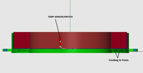
Heat Sink with Cooling: Similar to above, if heat sink with convection not enough to control temperature, a cooling path can be designed into a structural holder for the coil.
In-line Cooling: Hollow core conductors are used to wind the coil and act as the electrical path and the cooling path. This allows for cooling to run through the coil itself and they are typically used in high-power applications.
Copper Tube Cooling: Depending on the size of the coil, copper tubing can be applied on the ID, OD, or in the center of the coil windings.
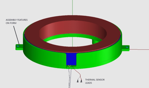
Temperature Sensor/Cut-off
Thermal sensors can be applied to a coil to monitor temperature and control operation when a coil gets too hot or rises beyond operational limits.
Sensor Types
- Thermocouples: Thermocouples can be applied externally on the coil or applied during winding at various internal points in the coil. Thermocouples monitor temperature and allow user flexibility in regard to actions taken when various temperature situations occur. They are typically integrated into the power supply system to monitor the coil temperature and determine whether to decrease power and/or shut down the system at various temperatures.
- On/Off Temperature Switch: These are on/off switches made to shut off power at a specified temperature. These can typically be applied externally on the coil and/or in line with the lead wire to the power source.
Custom Electrical Coils From Custom Coils
At Custom Coils, we specialize in creating high-performance electrical coils with sufficient cooling solutions for long-term operations. Contact us today to learn more about our capabilities or request a quote to start your order.
What is High-Density Plasma Technology?
Comments Off on What is High-Density Plasma Technology?High-density plasma domes have traditionally been used as decorative objects due to their unique lighting effects, but they are also an integral part of the semiconductor manufacturing industry. This blog will explain high-density plasma domes and their modern applications in further detail.
High-Density Plasma Domes
Also called a plasma globe, a plasma dome is a clear glass ball or container filled with a mixture of different noble gasses and a high-voltage electrode at the center. Plasma forms within the container when you apply voltage. Consequently, plasma filaments extend from the central electrode to the inner walls of the glass insulator. The result is the appearance of several beams of colored light.
Different variations of high-density plasma domes exist. The most common variation is a clear glass sphere filled with gas mixtures at close to atmospheric pressure. These gas mixtures may include neon, krypton, xenon, and argon.
The globes run on high-frequency alternating current. In most cases, the driving circuit is a type of power inverter, where a lower-voltage direct current supplements the inverter’s output with the help of a high-voltage, high-frequency transformer.
Applications of High-Density Plasma Domes
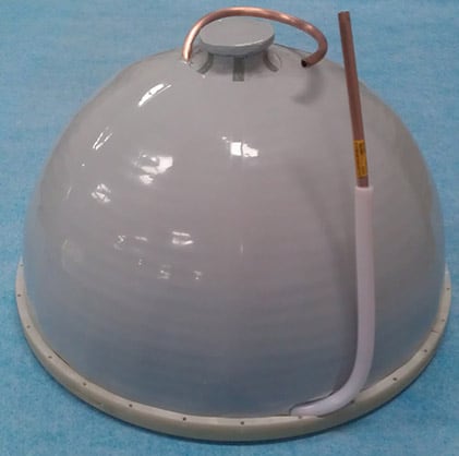
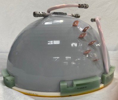 A high-density plasma dome is a single unit made up of several components, including:
- A ceramic bell jar
- A cooling/RF coil
- Ground tabs/slugs
- Machine parts
- A non-conductive elastomer
In semiconductor applications, high-density plasma chemical vapor deposition (HDP-CVD) is a technique that creates the crucial layers of insulation that separate and protect the electrical components. High-density plasma domes can be categorized based on the type of gasses they contain and their applications, which typically include RF assemblies and silicon wafers.
In addition to decorative and recreational purposes, high-density plasma globes can be part of an institution’s lab equipment for demonstration purposes. In particular, high-density microwave plasma machines can produce ions and free radical species. In these applications, the machine is made of a plasma source, the circuit, and the applicator.
High-density plasma domes can also be used in silicon wafer and RF assembly applications, where they are susceptible to damage with regular use. That’s why it’s important to partner with a reputable refurbishment and repair company.
 When using high-density plasma domes, exercise caution especially in the following conditions:
- Avoid bringing flammable items near the globes.
- The domes may emit certain frequencies that interfere with phone and Wi-Fi signals. Therefore, keep them away from such areas.
- Since they radiate electromagnetic waves, avoid operating the domes near people with pacemakers.
Custom Coils Capabilities
If you’re looking for high-density plasma dome repairs and refurbishments, Custom Coils is here to help. With over 30 years of experience, we are experts at developing high-quality, repeatable production processes for high-density plasma domes. We have shipped over 10,000 high-density bell jar parts, and we remain ready to take on any repair or refurbishment project, no matter how challenging or complex. What sets us apart from other suppliers is that we understand how critical parameters relate to material makeup.
Contact us to learn more about our capabilities, or request a quote to begin your project.