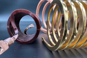
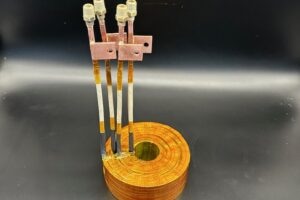
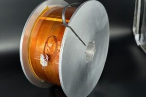
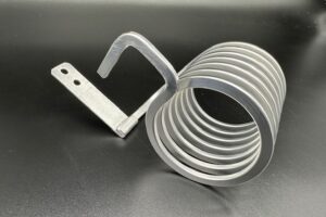
Our customers typically approach us with a range of electromagnet design applications in varying stages of development. Some specify precisely what is needed for their electromagnetic coil conductor, while others are looking for assistance determining optimal coil design. Regardless of a customer’s knowledge of material and design considerations, our experienced team is ready to help.
This guide will give you insight into important design features to consider in your application to achieve the operational performance and quality design that you require.
Determining the Magnetic Field of Your Electromagnetic Coil
The main function of an electromagnet is to produce a magnetic field with the defined strength and location required for your application. The strength and location of the magnetic field of an electromagnetic coil is based on:
- Number of wire wraps or turns on the coil
- Amperage applied to the coil
- Coil geometry (e.g. gauge, cross-sectional profile, size, etc.)
Magnetic field is a function of ampere-turns, or amp-turns, which is calculated by multiplying the number of coil turns by the input current, measured in amperes.
Types of Coil Winding
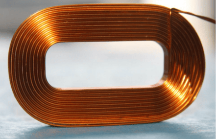
Coil winding refers to how the wires are wound or wrapped. The more times a wire is wrapped and the way in which it is wrapped affect coil performance. Some coils have hollow centers, or air cores, and are fully self-supporting. Some may be wound around a supportive bobbin. Others use wire wrapped around a magnetic metallic core to increase magnetic force. Core materials may include iron, cobalt, nickel, steel, or alloys of these. The coil can consist of one or more layers of wire, depending upon the application.
The winding type depends on various factors, such as coil size, number of turns (i.e., how many times the wire is wound around the core), number of parallel wires required, the cross-sectional shape of the completed winding, cooling method employed, and more.
Common winding types include:
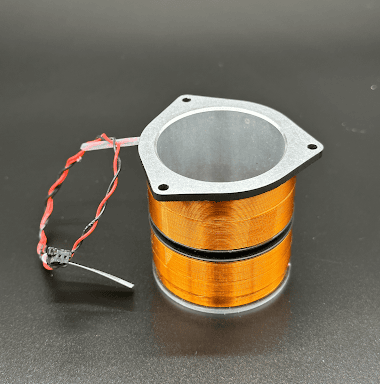
Bobbin
The wire is wrapped around a cylindrical bobbin. The bobbin shape defines the space in which the coil is wound and supports the turns. It also establishes fixed dimensions and features to facilitate assembly requirements. These are often used in switch-mode power supplies and power conversion units.
Learn More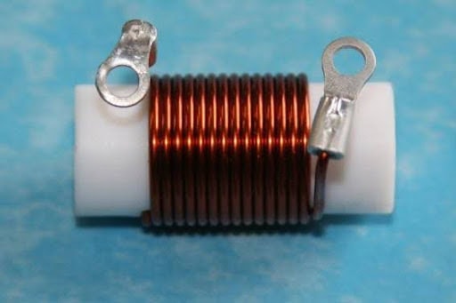
Helical
Helical winding involves winding the wire in a spiral pattern, typically around a core or as a self-supporting fixed coil. This method is often used in applications such as solenoids and antennas. Helical coil winding provides a compact and effective wind compared to random or wild winding.
Learn More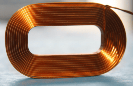
Orthocyclic
Also referred to as perfect-layer winding, in this method the wire is wrapped in layers with each successive layer resting in the gaps of the layer below, creating a hexagonal cross-section. This method has a 90% fill factor for round wires, providing the most compact packing for optimal resistance and thermal efficiency.
Learn More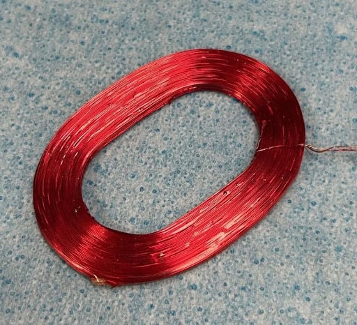
Wild Coil Winding
The most cost-effective and basic winding, wild winding allows for the wire to randomly wind within a defined space. The random placement of wire results in a wider distribution of wire lengths and a broader range of electric coil resistances. This method is often used for high-volume production and in ignition and relay systems, small motors, and small transformers, where more winding precision is not required.
Learn More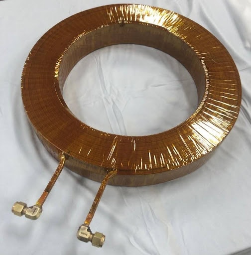
Upset Coil Widing
This technique allows for the wire leads to exit from the coil OD. This is employed when the design and assembly do not allow for or require the coil to maintain fixed and flat side surfaces, unobstructed by the leads. This technique is most often used with larger shaped (square/rectangle) conductors with limited space for lead routing and termination.
Learn MoreDesign Recommendations
At Custom Coils, Inc., we work with critical specifications and all available design inputs to evaluate and recommend the best options for your project. Our approach is comprehensive and includes an analysis of materials and manufacturing details of the coil, power considerations and cooling requirements, and next-level assembly. Design review, revision, prototyping, and testing are included based on the stage of project development.
In addition to critical specifications and requirements, we also consider the following factors for each project:
Performance and Quality
Providing manufacturing inputs to meet or improve quality and performance in the coil design. Depending on the coil operational requirements, material process or design recommendations can increase the operational performance and quality.
Manufacturability
Considering the design in terms of its ability to be manufactured efficiently, with minimal waste, failure, or error. This may involve modifications to the original design to reduce complexity or steps in production without impacting quality and performance.
Cost-Effectiveness
Design flexibility can improve overall costs. For example, expanding tolerances, while not sacrificing performance, and expanding material options where available help to maximize cost containment.
Process Stage
Depending on your coil project’s stage of development, functional or proof-of-concept prototyping, testing, and validation may be appropriate. These steps may uncover process inefficiencies, design flaws, or other issues prior to final production.

